
Choosing a Valve Water Meter is not just a matter of matching pipe size. The right choice depends on flow range, pressure, water quality, installation space, and the way readings will be used. A meter that performs well in a clean test line may behave differently in a building with rusty pipes, sudden demand changes, or limited access for maintenance. Small details matter.
Measurement pioneer Lord Kelvin is widely quoted: “When you can measure what you are speaking about, and express it in numbers, you know something about it.” That principle fits water-meter selection. Buyers should compare documented accuracy, operating range, pressure loss, materials, and connection types—not rely on a product label alone. Ask for test data and clear installation guidance. Check whether the meter supports the required reading method, such as a local dial or remote output. A valve-equipped design can simplify shutoff and servicing, but its layout still needs to suit the actual pipework.
This guide presents seven practical tips for choosing a Valve Water Meter, from confirming demand to reviewing maintenance needs. It also highlights details that are easy to overlook, including room around the valve handle and the direction of flow. A checklist helps, but it cannot replace site measurements or manufacturer documentation. There is no perfect meter for every system. The useful choice is the one that fits the real operating conditions, even when those conditions are less tidy than the specification sheet suggests.
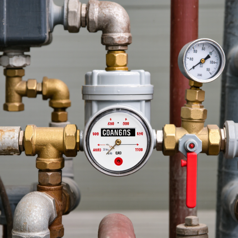
A valve water meter combines flow measurement with a valve that can isolate or regulate supply. The valve may be manual or motorized; the measuring element may be mechanical, ultrasonic, or electromagnetic. Mechanical meters use moving parts and suit many ordinary service lines. Ultrasonic meters have no internal rotor, which can reduce wear, but their readings depend on correct installation and suitable flow conditions. Electromagnetic models need conductive water and a compatible power setup. Different jobs, different meters.
The World Bank’s 2006 report, The Challenge of Reducing Non-Revenue Water, estimated average water losses at about 35% in developing-country systems and 15% in developed-country systems. These figures describe system-wide losses, not meter error alone. Still, accurate meters help utilities identify unusual consumption and support water audits.
A meter cannot fix a leaking pipe. That distinction matters.
Tips: Match the meter’s flow range to real demand, including low nighttime flow. Check pipe size, pressure, water quality, and available power before choosing a valve actuator. Leave room to reach the meter and valve for testing or service. Ask for calibration and accuracy data under recognized testing standards, such as OIML R 49. And check the installation manual; even a capable meter can misread when fitted poorly.
Choosing a valve water meter starts with the system’s actual flow, not just the pipe diameter. A meter sized only to match a pipe can miss small flows or restrict heavy demand. Do not guess. Record typical use and likely peaks, such as several taps running while an irrigation zone is active. Include quiet periods too. Nighttime flow can reveal small, steady use that a meter with a high starting threshold may not register.
Compare the expected minimum, normal, and peak flow with the meter’s published operating range. The minimum matters for leak detection; the maximum continuous rating matters during busy periods. Leave a reasonable margin, but avoid oversizing without a reason. A meter that is too large may measure low flows less reliably, depending on its design. Check pressure-loss data as well. A tight valve-and-meter assembly can leave weak flow at a distant shower. Specifications vary, so confirm the selected meter’s flow limits and installation requirements with a qualified water-system professional. Field readings may not match estimates perfectly; that is a reason to verify, not to ignore the data.
A valve water meter must suit the pipe, not just the catalogue. Check whether the valve is for isolation or flow control; a partly closed valve can disturb flow and affect readings. The AWWA manual M6, Water Meters—Selection, Installation, Testing, and Maintenance, recommends considering meter type, installation, and operating conditions together. Keep the meter accessible for testing, and follow its specified straight-pipe requirements. Small layout details matter.
Match wetted materials to water chemistry, temperature, and pressure. Corrosion, sediment, or scale can damage moving parts and narrow the valve passage. For potable-water systems, verify that materials meet the applicable local health requirements. OIML R 49-1:2013 sets class 2 meter error limits of ±5% in the lower flow range and ±2% in the upper range. These are test limits, not a promise that every installation will perform that way.
Record minimum night flow, peak demand, and expected pressure before choosing a size. A meter selected only for peak flow may under-read household trickles; one selected too small can create excess pressure loss. Check the valve’s pressure rating and the meter’s operating range against real site conditions, including occasional surges. Then compare the manufacturer’s loss curve with the system’s available pressure. A neat specification can still miss an awkward installation. It happens.
Tip 1: Check the accuracy curve, not just the headline accuracy. A meter may perform differently at low and peak flow. Compare its stated error range with your expected demand, including overnight trickles and short valve cycles. EPA WaterSense estimates household leaks waste nearly 10,000 gallons annually; this is not a meter-error figure, but it shows why detecting small flows matters.
Tip 2: Ask for traceable test results and applicable certification. ISO 4064 and OIML R 49 specify requirements and test methods for water meters. Confirm the exact model and size are covered, and check whether local authorities accept the certification. A logo alone proves little.
Tip 3: Match the meter to the installation. Check pipe diameter, connection type, flow direction, pressure, temperature, and permitted mounting position. For a meter with an integrated shutoff valve, verify valve operation and whether it restricts flow. Also confirm pulse or remote-reading outputs match your monitoring system. I would recheck real operating conditions before ordering; a technically certified meter can still be a poor fit. Read the datasheet closely.
| Tip | What to check | Practical selection guide |
|---|---|---|
| 1. Match the meter to the expected flow | Check the meter’s permanent flow rate (Q3), minimum flow rate (Q1), and flow range. The range ratio, R, is Q3 divided by Q1. | Compare the site’s normal and peak flows with the meter’s rated values. Do not size a meter from pipe diameter alone; an oversized meter may be less effective at registering low flows. |
| 2. Verify measurement accuracy | Review the stated accuracy class and allowable error limits across the applicable flow range. Under ISO 4064 and OIML R 49 frameworks, performance requirements distinguish flow ranges and meter classes. | Ask for test documentation for the exact model and operating conditions. Confirm that the stated limits meet local regulations and the application’s billing or monitoring requirements. |
| 3. Confirm approvals and potable-water suitability | Check approvals required in the country or region of installation, plus documentation for materials that contact drinking water. | Requirements vary by market. Examples of relevant frameworks include ISO 4064/OIML R 49 for water meters and NSF/ANSI/CAN 61 for drinking-water system components in markets where it is recognized. Verify current local acceptance and the product’s scope of approval. |
| 4. Check valve and meter compatibility | Confirm the valve’s open and closed flow capacity, connection type, installation direction, and whether the valve is integrated with or installed separately from the meter. | Ensure the valve does not create an operating restriction that conflicts with the required flow. Follow the manufacturer’s installation instructions for orientation, upstream and downstream conditions, and any required straight pipe lengths. |
| 5. Match pressure and temperature ratings | Compare the system’s working pressure, possible pressure surges, and water temperature with the meter and valve ratings. Check the pressure class, such as PN, where applicable. | Choose ratings that cover the actual service conditions and applicable code requirements. Do not assume a pressure or temperature rating is universal; confirm it on the product documentation. |
| 6. Confirm materials and connection dimensions | Check body and wetted-part materials, corrosion resistance, nominal size, thread or flange standard, and the available installation space. | Match the connection standard and dimensions to the existing pipework. For drinking-water use, verify that wetted materials are approved for the intended water and jurisdiction. |
| 7. Plan reading, maintenance, and verification | Check register units, display visibility, pulse or communication outputs if needed, battery or power requirements, service access, and verification intervals. | Confirm that readings can be collected reliably at the installation site and that the meter can be isolated or removed for inspection when required. Note that 1 m³ equals 1,000 litres when comparing display units. |
A valve water meter should be judged by more than its purchase price. Compare seven practical points: pipe compatibility, flow range, installation space, access for reading, shutoff arrangements, maintenance needs, and expected service life. Check the pipe diameter and normal flow before selecting a model. A meter that is poorly matched may give unreliable readings or restrict flow. Measure the space around the pipe, too. Technicians need room to install fittings and remove the meter later. Small details matter.
Installation costs include labor, connectors, site access, and any planned downtime. Ask whether the meter can be fitted without changing nearby pipework. Confirm its required orientation and whether upstream filtration is recommended. These requirements vary by design, so consult the technical documentation rather than assuming all meters install alike. Maintenance costs may include cleaning, inspection, testing, or replacement parts. Consider how easily staff can reach the valve and meter in a cramped utility room. Access can save time. Or become a recurring headache.
For lifecycle costs, estimate the purchase, installation, maintenance, and eventual replacement costs over the same period. Include the cost of inaccurate readings if water use informs billing or leak checks. A low-cost meter may not be the economical choice if it needs frequent attention. Still, forecasts are imperfect: actual water quality, usage, and installation conditions can change maintenance needs. Compare supplier specifications with your own operating records, and leave room in the budget for the unexpected.
Compare installation, maintenance, and estimated 10-year lifecycle costs for three valve-equipped meter options.
How to read this: Illustrative USD planning estimates per meter for a typical 1-inch service, not supplier quotes. The 10-year total combines initial meter, valve, and installation cost with estimated maintenance and replacement allowance. Actual costs vary by location, meter size, labor, water quality, and local requirements.
Seven selection checks: Confirm pipe size and fit; verify flow range and accuracy needs; check valve compatibility and access; compare installed cost; review maintenance and calibration needs; confirm power, communications, and replacement-part availability; estimate total cost over the expected service life.
Contact Us