
Vacuum brazing joins metal components without melting their base materials. In a sealed furnace, pumps remove air and reduce oxidation while parts heat under a controlled cycle. The filler alloy melts, flows through close-fitting joints by capillary action, and solidifies during cooling. Small gaps matter. So does surface preparation.
The Vacuum Brazing Process is valued for clean joints, repeatable heating, and assemblies with complex shapes. It is used for components such as heat exchangers, aerospace hardware, and medical equipment. But vacuum alone does not guarantee a sound bond. Alloy choice, joint clearance, furnace uniformity, cleanliness, and cooling rate all affect results. A fingerprint or misplaced support can create a defect that is hard to see.
For process guidance, the American Welding Society’s AWS C3.6M/C3.6, Specification for Furnace Brazing, sets requirements for furnace-brazed assemblies. ASM Handbook, Volume 6A: Welding Fundamentals and Processes, provides technical coverage of brazing methods and material behavior. These references help engineers define operating controls and inspection criteria; actual parameters still depend on the alloy and part design. In this guide, we trace the cycle from preparation and pump-down to heating, filler flow, cooling, and quality checks. The practical details are not glamorous. They are where reliability is won—or quietly lost.
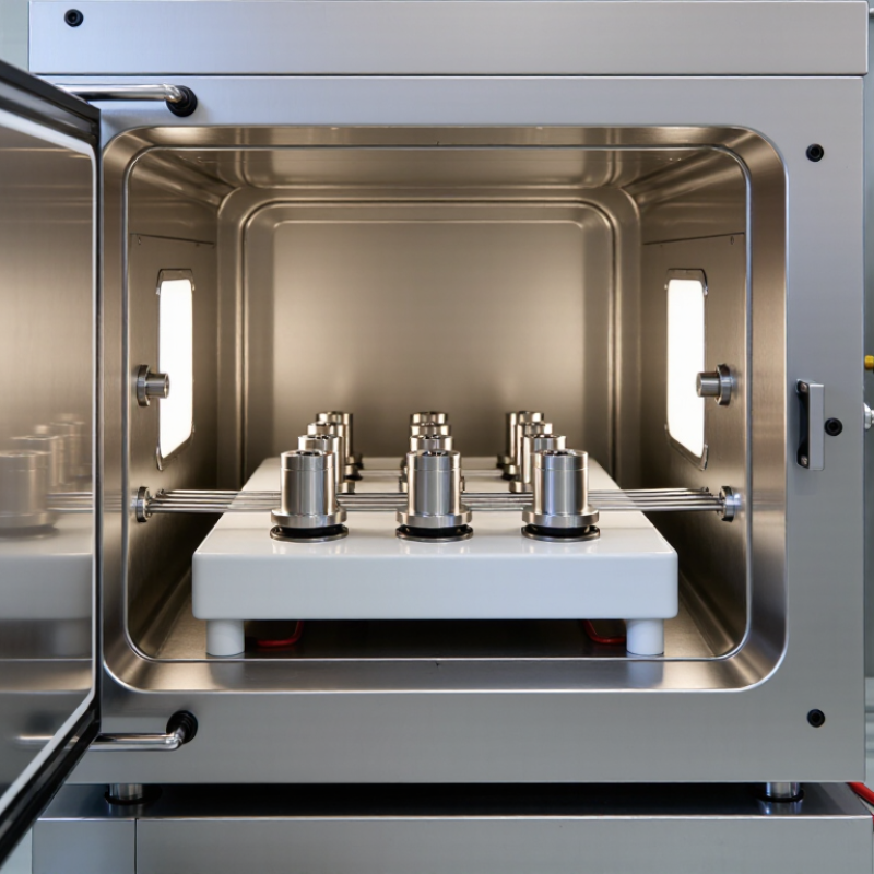
Preparing Components and Selecting the Filler Metal
Vacuum brazing rewards careful preparation. Oil, fingerprints, and machining debris can disrupt wetting or leave residue inside the chamber. Clean each component, remove oxide using a method suited to its alloy, and dry it fully. Even a thin film matters. Check joint faces for burrs, flatness, and consistent alignment before assembly. A small gap can change how molten filler flows.
Joint clearance needs measurement at brazing temperature, not just on the bench. The AWS Brazing Handbook describes clearances around 0.001–0.005 inches (25–125 μm) as common guidance for many brazed joints; the suitable range depends on materials and design. Close enough. But not blindly close. Select filler metal for compatibility with both base metals, service temperature, corrosion exposure, and vacuum conditions. AWS A5.8/A5.8M classifies brazing filler metals by composition, providing a useful starting point rather than a substitute for testing. In vacuum, volatile constituents deserve particular scrutiny. A test coupon can reveal poor flow or brittle joints before production, though it may not reproduce every real-world thermal cycle. That uncertainty is worth admitting. Carefully recorded trials make the choice more reliable.
A sound vacuum-brazed joint starts with surfaces that fit closely and stay clean. Remove oil, oxide, and loose particles using a process approved for the base materials, then handle parts with clean gloves. Even a small fingerprint can leave residue that interferes with wetting. The AWS Brazing Handbook describes typical capillary clearances of about 0.001–0.005 inch for many brazing applications; the right value depends on alloy, temperature, and materials. Check the filler-metal and engineering specifications rather than treating that range as universal.
Position the filler metal where capillary action can draw it through the joint. Secure the assembly with clean, vacuum-compatible fixtures, allowing for thermal expansion and avoiding excessive restraint. Keep parts spaced so heat reaches them evenly, and arrange the load to avoid blocking the furnace’s heating elements or sensors. Dry components before loading: moisture and trapped residues can outgas under vacuum. A neat-looking setup is not always a reliable one; fixture contact and joint gaps deserve a second inspection.
Tips: Photograph the assembled load, record joint clearances and part positions, and note any unusual fixture contact. These simple records help explain inconsistent results later. Don’t overpack the furnace. Check the furnace procedure for approved load limits and placement guidance before starting the cycle.
Before heating, technicians clean the joint surfaces and place the parts with the brazing filler in a stable fixture. Oil, fingerprints, or trapped moisture can release gases inside the furnace. Small details matter.
The chamber is sealed, and vacuum pumps remove air and other gases. Operators watch the pressure gauge and check for leaks before starting the cycle. If pressure does not fall as expected, heating should wait; a rushed cycle can leave contamination or weak joints.
Once the vacuum reaches the level specified for the materials and furnace, the temperature rises in controlled stages. A gradual ramp helps reduce thermal stress and gives remaining gases time to escape. The parts then reach the filler metal’s brazing range, where the filler melts and flows through the joint by capillary action.
The required temperature and hold time depend on the alloy, joint clearance, and part mass. Not perfectly, though: uneven loading or a poorly placed thermocouple can make the actual part temperature differ from the display. After the hold, controlled cooling limits distortion. The chamber usually remains under vacuum, or uses a suitable clean atmosphere, until the parts are cool enough to avoid oxidation.
During vacuum brazing, carefully cleaned components are assembled with filler metal near the joint. The furnace removes much of the air, helping limit oxidation as the parts heat. The temperature rises above the filler metal’s melting point but stays below the base metals’ melting points. Small gaps matter.
Once molten, the filler metal wets the component surfaces and flows into the joint through capillary action. A consistent, narrow clearance helps it spread rather than pool at the edges. The metal then fills the gap and bonds with both surfaces. In practice, even a well-controlled furnace cannot compensate for poor fit-up or residue. That detail is easy to underestimate. After a measured hold, the assembly cools, and the filler solidifies into a continuous joint.
Tips: Clean parts thoroughly, keep joint clearances consistent, and position filler where it can reach the full seam. Follow a qualified heating cycle for the specific materials. Check sample joints for gaps or uneven filler flow; one successful run does not prove every assembly is sound.
After brazing, the assembly should cool under controlled conditions before the furnace is opened. Cooling too quickly can create thermal gradients, distortion, or stress, especially in parts with different thicknesses. Follow the qualified cycle and confirm the load temperature with the furnace’s recorded data; there is no safe unloading temperature that fits every alloy and assembly. The AWS Brazing Handbook gives typical capillary joint clearances of about 0.001–0.005 inch (0.025–0.127 mm) for many applications. That range is a useful reference, not a substitute for the approved design.
Tips: Let the load stabilize before unloading. Wear suitable heat protection, and keep parts supported as they cool. Record the actual temperature and cycle time. A neat-looking fillet can still hide an incomplete joint.
Inspect the assembly only after it is cool enough to handle safely. Check for cracks, discoloration, excess filler, blocked passages, and visible distortion. Compare critical dimensions with the drawing, then use an appropriate nondestructive test when the component’s service conditions require it. ASTM E165/E165M describes liquid penetrant examination for surface-breaking discontinuities in nonporous materials; it cannot reveal flaws beneath the surface. I would not sign off on appearance alone. Record findings and investigate any indication that falls outside the acceptance criteria.
| Stage | Typical Practice | What to Check | Useful Process Records |
|---|---|---|---|
| Controlled cooling | After the brazing hold, cool the load according to the approved cycle. Cooling may use furnace radiation, controlled gas cooling, or another qualified method. The appropriate rate depends on the alloy, component geometry, joint design, and any required heat treatment. | Confirm that the cooling profile follows the approved procedure and that the parts are supported to limit distortion. Avoid rapid cooling unless it has been qualified for the materials and assembly. | Cooling curve, thermocouple readings, furnace-cycle identification, and any alarms or cycle deviations. |
| Temperature check before venting | Keep the chamber under vacuum or a specified protective atmosphere until the load reaches the procedure’s permitted venting temperature. The limit is process-specific; there is no single temperature suitable for every alloy or furnace. | Verify the indicated load or furnace temperature—not just the elapsed cooling time—before introducing gas or opening the chamber. | Temperature at venting, atmosphere or gas used, and the applicable procedure revision. |
| Chamber venting | When permitted by the cycle, restore the chamber to atmospheric pressure using the specified gas, commonly a clean inert gas such as argon or nitrogen where appropriate. | Check that the venting method matches the material and cleanliness requirements. Prevent exposure to air while parts are still hot if oxidation could affect the assembly. | Venting gas, chamber pressure status, and any atmosphere or cleanliness checks required by the process. |
| Unloading and handling | Remove the load only after the chamber is safe to open and the components are cool enough for the prescribed handling method. Use clean gloves or suitable handling tools when surface contamination is a concern. | Look for loose fixtures, shifted components, visible discoloration, damage, or signs of distortion. Handle the assembly carefully to avoid bending joints or contaminating clean surfaces. | Load identification, unloading time, operator, fixture condition, and any visible observations. |
| Visual and dimensional inspection | Inspect accessible joints and compare critical dimensions with the engineering drawing or inspection plan. Magnification may help reveal surface indications, but visual inspection cannot establish the condition of every hidden joint. | Check for incomplete filler-metal flow, excessive filler metal, cracks, visible voids, distortion, and blocked passages where applicable. Assess dimensions against specified tolerances. | Inspection results, measurement values, photographs when required, and any nonconformance reports. |
| Functional or nondestructive testing | Use tests selected for the assembly’s function and acceptance requirements. Examples include pressure or leak testing, radiographic examination, or other qualified nondestructive methods. | Apply the specified test method, test pressure or sensitivity, duration, and acceptance limits. These requirements must come from the drawing, customer specification, or approved quality plan. | Test method, equipment identification, calibrated instrument status, measured results, and pass/fail disposition. |
| Final release | Review the furnace-cycle record and inspection results before accepting the assembly for the next operation or shipment. | Confirm traceability, completion of required checks, and documented disposition of any deviations. Do not treat a visually sound joint as proof of leak-tightness or internal integrity. | Final inspection approval, material and load traceability, cycle record, and signed release status. |
Typical practices vary with the base metal, filler metal, joint design, component requirements, and qualified furnace cycle. The approved process specification and acceptance criteria take precedence.
Contact Us